The goal of this project was to develop the Augmented Reality Expert Demonstration Authoring (AREDA) product to provide a simple and intuitive method for rapidly authoring AR work instructions by tracking and recording the actual part manipulations of an expert using 3D cameras with advanced image processing and computer vision algorithms. This was achieved through tracking and recording the actual part manipulations of an expert using 3D depth cameras with advanced image processing, computer vision and point cloud matching algorithms.
An expert trains AREDA with an assembly operation, which includes steps such as: a) Background-area-skin calibration, b) CAD and point cloud part library uploads, c) Record a sequence of assembly steps, d) Automatically generate assembly steps while matching the parts recorded by the camera against the uploaded CAD parts, and e) Refinement stage to modify if there were errors in automatic part detection and animation sequences in assemblies. Once the expert generates these assembly instructions within AREDA, they can be passed on to an assembly operator who can visually see and follow the steps for assembly operations.
Technical features of AREDA
User detection and tracking
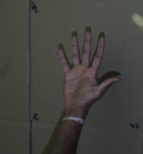
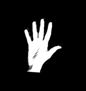
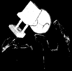
The calibration steps requires filtering the background work surface and segmenting hand/skin within the depth camera’s field of view. Multiple users with different skin colors, gloves, or long sleeves are categorized as “hypotheses”, and each hypothesis was modeled as a Gaussian Mixture Model (GMM) coordinated by Particle Swarm Optimization under the hood. The PSO-GMM method allows for multiple Gaussian distributions to be created and solved in real-time, eliminating the need for user input. Figure 1(a) shows the RGB version of skin tone captured by the depth camera. Figure 1(b) shows processed skin tone with background work area filtered out. Figure 1(c) shows an assembly sequence with background filtered and skin mostly eliminated.
 |
 |
 |
|
Figure 1(a). Hand capture footage by the depth camera |
Figure 1(b). Skin tone processed with background removed |
Figure 1(c). Skin tone identified and filtered from an assembly using PSO-GMM |
Point cloud generation and object detection
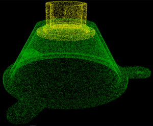
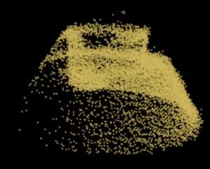
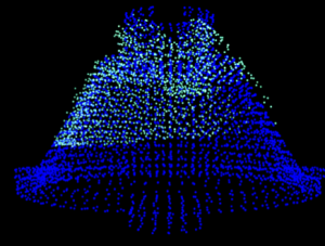
The AREDA system uses the DFP hardware system to capture 3D frames of the assembly environment. All CAD parts and their corresponding point clouds are uploaded within the AREDA interface. These are saved in an internal SQL database. The DFP hardware system captures the scene as viewed by the depth camera, which includes the work area, the surroundings, and the parts that are brought into the work area for assembly. Object recognition requires that all extraneous details except the part(s) to be assembled are filtered out. Using RANSAC and clustering algorithms, only parts that are within the work area are saved and the rest of the data is discarded. Every new part that the expert introduces to the scene is considered an assembly component candidate. The point cloud that is associated with this candidate is then stored and matched to reference objects prepared in advance from CAD models of the parts using the Iterative Closest Points (ICP) method. ICP solves a least-squares problem to align two sets of points in an iterative optimization process. Upon completion, an ICP match generates a fitness score to indicate how good the camera-projector point cloud matches against a CAD part. A lower fitness score indicates a better match. Figure 2(a) shows CAD the point cloud of a CAD part within a bench-vise assembly. Figure 2(b) shows the point cloud generated by the depth camera from its view for the part after noise filtering. Figure 2(c) shows both the clouds ICP matched and aligned, with the denser points in blue representing the CAD part’s cloud, and the blue-green points representing the depth camera’s point cloud.
 |
 |
 |
| Figure 2(a) Point cloud for the CAD part |
Figure 2(b) Depth camera generated point cloud for the part after noise filtering |
Figure 2(c) Merged and aligned CAD and depth camera cloud |
AREDA Demonstration
The video below shows a demonstration of how AREDA works.
Impact
The system was based on existing successful research results from the proposers. Through cost-sharing partnership with aerospace (Boeing) and heavy equipment (Deere) sectors, functional requirements for AREDA were developed. Product requirements based on market opportunities were gathered from other project partners (DAQRI and Design Mill). Inter University collaboration (Purdue) afforded the opportunity to implement cutting edge depth camera sensors for use within AREDA. AREDA was developed at a level commensurate with TRL 6 in an attempt to bring these new methods to commercialization faster. This is a key innovation that will accelerate AR adoption in manufacturing, which in turn will reduce time to author work instructions, enhance their communication to the shop floor, reduce process errors, and decrease manual process time – all of which will substantially improve US manufacturing productivity and competitiveness.